NSEE PY600 AC Residential Operator Rack and and 49 similar items

Free Shipping
17 recent views
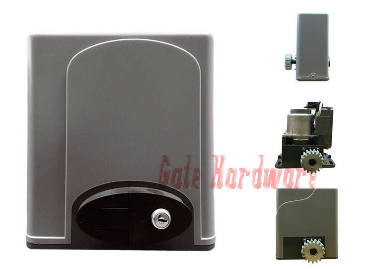
NSEE PY600 AC Residential Operator Rack and Pinions Slide Gate Door Opener
$509.95
View full item details »
Shipping options
Seller handling time is 2 business days Details
FREE in United States
Offer policy
OBO - Seller accepts offers on this item.
Details
Return policy
Full refund available within 30 days
Details
Purchase protection
Payment options
PayPal accepted
PayPal Credit accepted
Venmo accepted
PayPal, MasterCard, Visa, Discover, and American Express accepted
Maestro accepted
Amazon Pay accepted
Nuvei accepted
Item traits
| Category: | |
|---|---|
| Quantity Available: |
2 in stock |
| Condition: |
New |
| UPC: |
747467111367 |
| Model: |
PY600ACU |
| MPN: |
PY600ACU (110v) |
| Application: |
Commercial |
| Horse Power: |
1400 lbs (600 kgs) |
| Maximum Door Weight: |
1400 lbs (600 kgs) |
| Maximum Gate Weight: |
1400 lbs (600 kgs) |
| Motor Loading Weight: |
1400 lbs (600 kgs) |
| Brand: |
NSEE |
| Type: |
Residential Operator Rack and Pinions Slide Gate |
| Voltage: |
110V (± 10%) |
Listing details
| Seller policies: | |
|---|---|
| Shipping discount: |
Seller pays shipping for this item. |
| Posted for sale: |
More than a week ago |
| Item number: |
1395689426 |
Item description
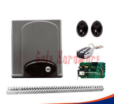
Basic Kit Includes:
1. Sliding Gate Operator (1) (Set) (110v).
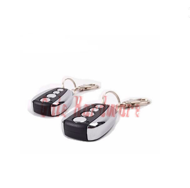
2. Remote Controller (2) (PCs).
3. Internal Hex-angular Bolt (4) (PCs).
4. Internal Hex-angular Bolt (4) (PCs).
5. Left Limit Iron (1) (PCs).
6. Right Limit Iron (1) (PCs).
7. Base (1) (PCs).
8. Release Keys (2) (PCs).
9. Manual (1) (PCs).
10. 15ft of Steel Rack (5 PCs).
11. Infrared Sensors (2) (PCs).
12. Inside Control Board (1) (PCs).
13. Magnetic Limit Switch.
1. Products
introduction
Please read the instructions carefully before proceeding.
MCU is supplied to control the gate operator.
Keypad / single button interface.
Photo beam safety beam interface.
User can select Auto-close function.
Manual key release design for emergency purposes.
2. Important safety information
Carefully read and follow all safety precautions and warning before
attempting to install and use this automatic gate operator.
Make sure the Power
supply(AC220V or AC110V) of the gate operator is suitable for the power supply
in your area.
3. Main technical
parameters
Type
GPY600AC
Power supply
220V,
50Hz
110V,
60Hz
Motor speed
55rpm
66rpm
Rated output power
of motor
200W
Remote control operating distance
30m / 100ft
(Frequency:433.92mHz)
Remote control mode
Single
button
Output shaft height
58.5mm / 2.3inch
Max. gate weight
600Kg / 1400lbs
Output torque
16N·m
Limit switch
Spring limit
switch or Magnetic limit switch
Noise
?56dB
Duty cycle
S2,
15 minutes
extra remote control
20
Environmental temperature
-20C / 68F~+50C / 122F
Gate Move speed
13m / 43ft /min
15m / 50ft /min
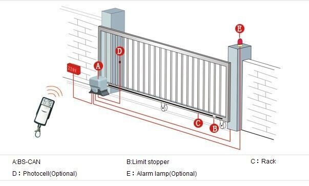
4. Mechanical Installation
The GPY600AC will handle gate weighting up to 600 kg and up to 8m / 26ft 12m if
the proper installation procedures have been followed.
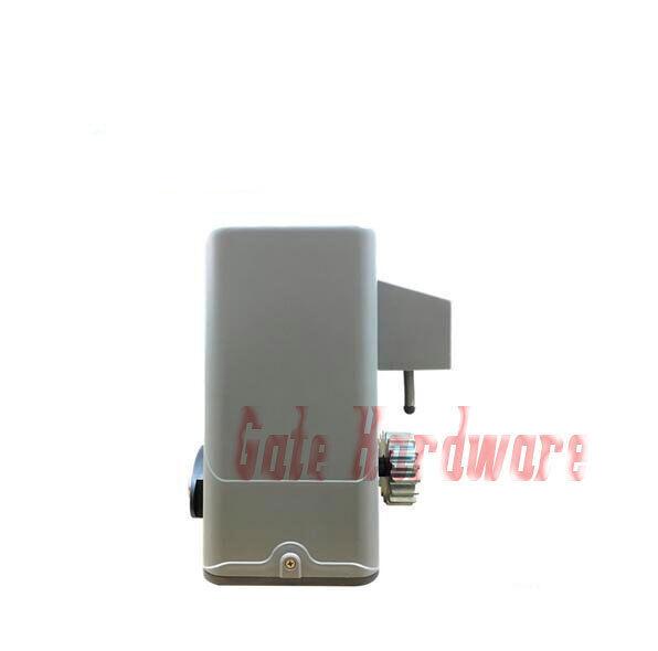
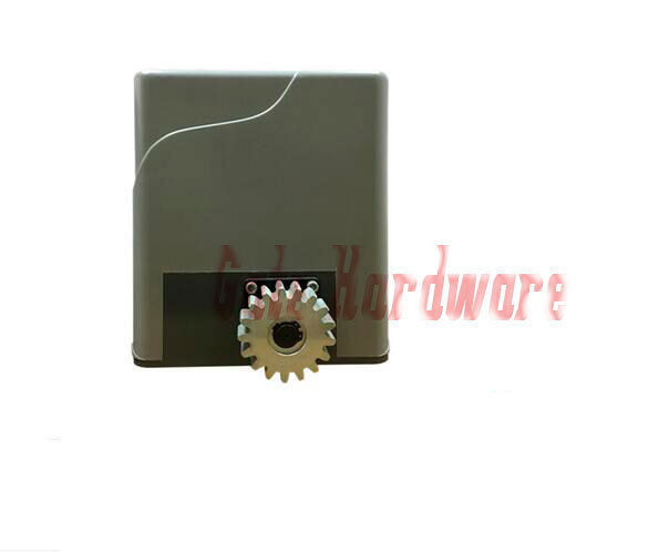
The GPY600AC gate operator operates by forcing a drive rack by a drive
gear. The entire configuration is shown
in the diagram below. The gate operator must be installed on the inside of the
gate.
Gate preparation
Be sure the gate is properly installed and
slides smoothly before installing the GPY600AC
sliding gate operator. The gate must be plumb, level, and move freely.
Conduit
In
order to protect the cable, use PVC conduit for low voltage power cable and
control wires. Conduit must be preset into the concrete when it is poured.
Wires within the conduit shall be located or protected so that no damage can
result from contact with any rough or sharp part.
Concrete pad
The
base unit of the gate operator requires a concrete pad in order to maintain
proper stability. The concrete pad
should be approximately 450mm x 300mm x 200mm deep in order to provide for
adequate weight and structure to insure proper stable installation.
Anchors
You
can use anchor bolts, anchors, washers and nuts. These anchors must be set into
the concrete when it is poured or you can use wedge anchors to fasten the
operator.
Operator base
After the concrete
has hardened, mount the gate operator base to the concrete pad. Verify that the
base is properly leveled.
Using bolts and
washers mount the gate operator to the base and insert the cover. Check the
operator and make sure it is lined up with the gate.
Installation of Rack
l
Fix the three nuts (in the same
package with rack) on the rack element.
l
Lay the first piece of rack on the gear and weld the
first nut on the gate.
l
Move the gate manually, checking if the rack is resting
on the gear, and weld the second and third nut.
l
Bring another rack element near to the previous one. Move
the gate manually and weld the three nuts as the first rack, thus proceeding
until the gate is fully covered.
l
When
the rack has been installed, to ensure it meshes correctly with the gear.
l The space between rack and gear is about 0.5mm.
5. Adjustment
Spring limit switch
l To ensure safety, it is recommended to
install limit switches at both ends of the gate to prevent the gate from
sliding out of the rails. The rails must be installed horizontally.
l Install the limit
block as shown in Fig.5 and Fig.6. The spring limit switch and blocks are used
to control the position of the gate.
l
Release
the gear with the key and push the sliding gate manually to pre-determine the
position, fix the block to the rack and lock the gear by push up the release
bar. Moving the gate electrically, adjust the block to the proper position until
the position of the opening and closing meet the requirement.
Magnetic
limit switch
l
To
ensure safety, it is recommended to
install limit switches at both ends of the gate to prevent the gate from
sliding out of the rails. The rails must be installed horizontally.
l
Install the limit block as shown in
Fig.5 and Fig.6. The magnetic of limit switch and blocks are used to control
the position of the gate.
l Release
the gear with the key and push the sliding gate manually to pre-determine the
position, fix the block to the rack and lock the gear by push up the release
bar. Moving the gate electrically, adjust the block to the proper position until the position of the opening and closing meet the
requirement.
Manual operation
In case of power
failure use key unlock the lock and pull down the release bar about 90 degree
to open or close gate manually, use the release key as follow:
l Fit the supplied key
in the lock.
l Turn the key and pull
down the release bar about 90to release the gear. (Note: Do not exceed 90, be careful
not to use too much force, otherwise the release bar will be damaged.)
l Open and close the
gate manually.
Note:
If the gate bumps the mounting post and cannot be electric opened, move the
gate a few inches by hand, thus you can release the gate with the key, open and
close the gate manually.
6. Wire Connecting
Make sure that the
power is OFF before making any electrical connections.
Remove the cover,
perform the wiring (See Fig.8 and wiring notes for control board) and replace the
cover again.
Wiring notes of
control board
a.
Power
Input(X1):E (Earth),L (Live),N (Neutral).
PY600AC: AC220V PY600ACU: AC110V
b.
Caution
light: connect caution light wire toD1 and D2(terminal X3)
PY600AC: AC220V
PY600ACU : AC110V
c.
Output
power supply: 24VDC, COM (COM), I.R. (N.C Infrared)
If the infrared beam
is interrupted during closing, the gate will reverse and open immediately. The
product is not factory equipped with an infrared device, the infrared output
signal must be N.C.
d.
Three-button
switch / single-button switch (keypad): The PY600AC is equipped with interfaces
for three-button switch and single-button switch (keypad).
To
install the keypad attach one lead of your keypad to ?CLS? of terminal X4 and
the other to the ?COM?. The keypad will function in single channel mode (the
DIP switch 1 should be turn to OFF).
For
three-button switch installation, use the terminals for multi-channel mode. Connect
open wire of external button switch to ?OPN? of terminal X4, connect close wire
of switch to ?CLS?, connect stop wire of switch to ?STP?, connect common wire
of switch to ?COM?.
Motor and capacitor (Terminal
X2, X3): V (com), U (Positive direction), W (Opposite direction), E (grounding),
C (capacitor)
7. Tuning and operation
Remote control
l The remote control works in a single channel mode. It has four buttons. The function of button 1, button 2? button3 and button 4 are the same. With each press of the remote
control button which has been programmed, the gate will close, stop, open or
stop cycle.
l You
can program/learn button 1, button 2, button 3 individually. You also can
program/learn two buttons or three buttons together, but you need repeat the
program/learn process if you want to use more than one button.
l Adding extra remote
controls (Learn): Remove the cover, press the learn button ?AN1?
(Fig.8), then the ?LED2? (Fig.8) will be on and
turn off, then press the remote control button which you want to use, the ?LED2?
will turn on about 2 seconds and then turn off again. The learning process is
finished.
Up
to 25 remote controls may be used.
l Erase remote controls: To erase all
existing remote controls, press and hold learn button ?AN1?, the ?LED2? turns on, release the button once the
?LED2? turns off. This indicates that all the remote controls have been erased
completely.
l Note: Press the ?OPEN?
button of external button switch or remote control button which has been
learned, the gate will open, the motor rotates clockwise, and the ?LED2? is turns on. The output voltage between ?D1
and D2? (terminal X3) is AC220V/110V, the voltage between ?V? and ?U? is
AC220V/110V. Press ?STOP? button or the same remote control button, the gate
stops running. And the ?LED2? is turns
off. Then press ?CLOSE? button or the same remote control button again, the
gate will close, the motor rotates anticlockwise, and the ?LED2? is turns on.
The output voltage between ?D1 and D2? (terminal X3) is AC220V/110V, the
voltage between ?V? and ?W? is AC220V/110V. Press the ?STOP? button or the same
remote control button, the gate stops running. And the ?LED2? is turns off.
l Verify open
direction:
If the gate does not move in the desired direction, then you will need to
reverse the motor operating direction, open the black plastic cover, you can do
this by exchanging wires ?U? and ?W?, ?OPLT? and ?CLLT?.
8. Programming Process
Table of the DIP-switch
Position
DIP-switch
Function SET
1
ON
Three-button switch
OFF
Single-button switch (the CLS and COM), OPN
and COM is ?open door? function also.
2
ON
When the 2 and 3 all ON, the Controller
haven?t Auto-close function. When the 2 ON and the 3 is OFF, auto-close time
is near 20 Sec. when the 2 OFF and the 3 is ON auto-close time is near 40
sec. when the 2 and the 3 is all in position, the auto-close time is near 60
sec.
OFF
3
ON
OFF
Note:
(1) You
must follow the operating instruction as above, any wrong operation is not
allowed during setting. If your device responds to your requested function
correctly, you have set the function successfully, otherwise repeat the above
setup instruction until your device responds to your expected function.
(2) If
the gate can not be moved, please check whether the gate is obstructed or the
gate is too weight.
Activities Covered in
this section
l Remote transmitter:
(description exceeds maximum possible length)
|
Why are we showing these items?
Booth
Gate Hardware & Equipment's Store All Pieces and Parts that you need!!! |
|


-
Refine your browsing experience
We can show you more items that are exactly like the original item, or we can show you items that are similar in spirit. By default we show you a mix.


This item has been added to your cart
 NSEE PY600 AC Residential Operator Rack and Pinions Slide Gate Door Opener added to cart.
2 available in stock
NSEE PY600 AC Residential Operator Rack and Pinions Slide Gate Door Opener added to cart.
2 available in stock
View Cart or continue shopping.
 Please wait while we finish adding this item to your cart.
Get an item reminder
We'll email you a link to your item now and follow up with a single reminder (if you'd like one). That's it! No spam, no hassle.
Already have an account?
Log in and add this item to your wish list.